Scientific study of the atmosphere has revealed that the CO2 in the earth’s atmosphere is a significant contributor to global warming. The important sources of atmospheric CO2 are emissions from fossil fuel electrical power generating plants and from combustion engines powering vehicles of all types. Currently, regulations do not limit CO2 quantities that may be vented from a refrigeration system.
The ozone depletion potential for all the natural refrigerants is zero. The global warming potential for these refrigerants is either zero, or very small. The global warming potential of CO2 is 1.0 (set to this value by definition), where in contrast the CFC and HCFC refrigerants have values generally exceeding 1,000.
CO2’s Physical Characteristics
The physical characteristics of CO2 are unique. The thermodynamic vapor compression refrigeration cycle, component design, system design, and operation are constrained by the characteristics of CO2, which are shown in Table 1. Note that the freezing point (triple point) of CO2 is – 56.6 °C (– 69.8 °F), and NH3’s freezing point is – 77.7 °C (– 107.8 °F), both in the same neighborhood.
However, the critical temperature of CO2 is 31.0 °C (87.8 °F) and 132.3 °C (270.1 °F) for NH3, much less than NH3’s. While the freezing point (triple point) for CO2 is not much different than NH3’s, the CO2 critical temperature is significantly less than that of NH3.
R-22, an HCFC whose production is now curtailed, was once a popular refrigerant for industrial systems. Refrigerants R-507A and R-404A are an azeotrope and blend, respectively, and both are HFCs. Their high GWP makes their future as refrigerants uncertain. NH3, despite its good thermodynamic characteristics, has disadvantages including toxicity and moderate flammability. These reasons now make CO2 a refrigerant worthy of consideration for many applications in industrial refrigeration systems
Figure 1 is a plot of saturation pressure versus saturation temperature for several refrigerants including CO2 and NH3, which shows:
- The absolute CO2 triple-point pressure 5.18 bar (75.1 psi) is above atmospheric pressure.
- The CO2 critical-point temperature is less than typical design condensing temperature.
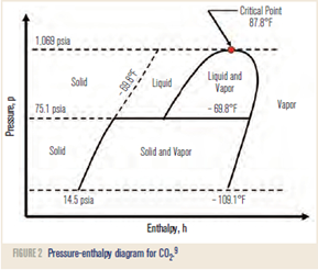
Note that CO2 is a low-temperature refrigerant (above atmospheric pressure at low temperatures) where in contrast, NH3 is an intermediate-temperature refrigerant. The CO2 phase diagram is shown in Figure 2 where only essential features are shown. Here the latent heat of CO2 is indicated by the horizontal distance between the saturated liquid and vapor lines. Comparison to R-22 reveals that the latent heat of CO2 is considerably higher than, but not as high as, NH3’s latent heat. Also, the CO2 pressure-enthalpy diagram shows that CO2 exists with high pressures and low temperatures—the top of the dome (critical point) is only 31.0 °C (87.8 °F).
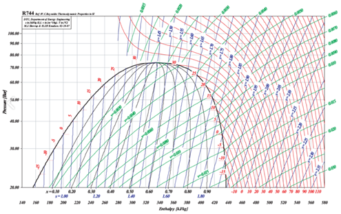
Figures 3 and 4 show the saturated liquid and saturated vapor lines for CO2 and NH3 on p-h (pressure-enthalpy) axes, respectively. These two charts and the characteristics mentioned above result in important and practical consequences when applying CO2 to industrial refrigeration.
Because of CO2’s high pressures, atmospheric air and water are not likely to enter the system. And, because CO2’s suction vapor density is high, compressors are small and evaporators operate with good performance. Further, observe (Figure 1) that the slope of the pressure-temperature curve for CO2 shows a much greater pressure change for the same temperature change.
In other words, pressure drops in CO2 result in much smaller temperature drops. For example, saturated CO2 vapor at – 42.8 °C (– 45 °F) with a 0.07 bar (1.0 psi) pressure drop has a corresponding 0.22 °C (0.4 °F) temperature drop.

| Source: | eJARN |